


How can I display the tank level inside the vehicle? In this article we explain how a tank level meter (gauge) works on a LPG tank and how you can replace the basic tank clock with a tank sensor with an electrical signal for the LPG switch or LED panel with level indication.
The following related tutorials complement this article:
LPG Vapor Tanks for RV Campers, Caravans and Food Trucks
Installation instructions for LPG cylinder tanks (vapor tanks) in (recreational) vehicles
What is an LPG Gas Bottle and what different types are there?
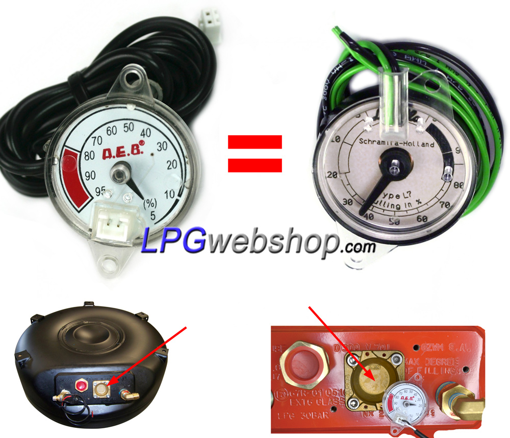
One of the 4 openings on a 4-hole LPG tank is intended for a tank float. The brass part of the tank float seals this opening via a rubber O-ring. The part that extends into the tank consists of a rod with an internal shaft, at the end of which is a float that moves with the level of the liquid LPG in the tank. The internal shaft rotates with the up and down movement of the tank float, thereby turning a magnet inside the external brass part. The dimensions of the internal parts (such as the length of the rods) vary depending on the dimensions and type of the LPG tank. Tank floats therefore come in all kinds of variants, so there is a suitable version for every type of LPG tank. This is because LPG tanks come in many different variants; Cylinder tank or Toroidal tank, Different diameter / tank height, with the tank valves at an angle of 52° (black LPG tanks) or at an angle of 105° (Red LPG vapour gas tanks).
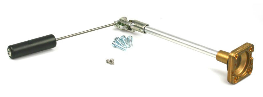
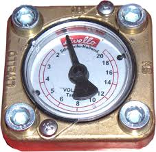
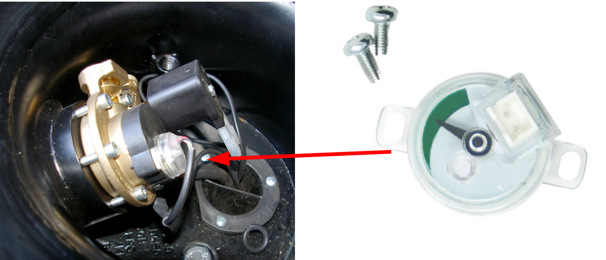
On the external brass part of the tank float, a tank gauge or tank sensor is placed, which also has a small magnet and thus follows and moves with the magnetic field of the tank float. The tank gauge or tank sensor fits onto the tank float in a specific form, meaning it essentially only fits one way and is secured by means of two screws. In this way, the tank content is displayed on the outside of the LPG tank.
Therefore, to exchange or replace a tank gauge or tank sensor, it is not necessary to dismantle the tank float or open the tank. The tank float (the brass part) thus always remains attached to the tank.
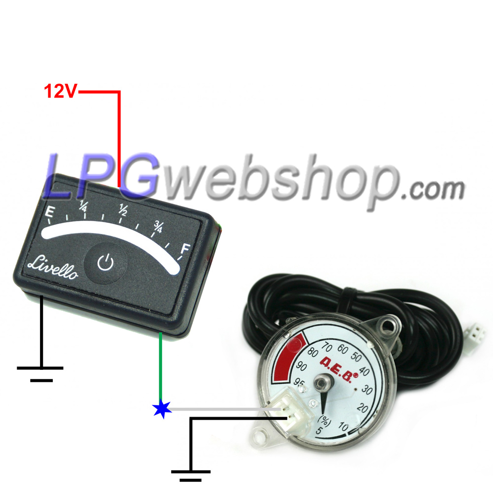
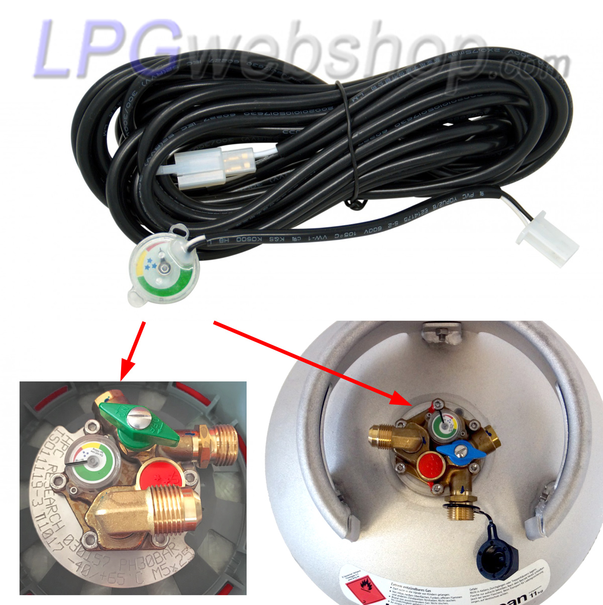
A tank sensor physically resembles a tank gauge very much, with the difference that it has an internal potentiometer (variable resistor) and wiring to connect it. The most common resistance range is 0 - 90 Ohm, where the 0% level (empty tank) corresponds to 0 Ohm resistance and the 80% level (full tank) corresponds to 90 Ohm.
A tank sensor makes it possible to connect it to an electric display such as an LED indicator and thus display the tank content, for example, on the vehicle's dashboard (or another location). It is, of course, important that the electric display (LED indicator) is compatible with the resistance range of the tank sensor and thus displays the correct content.
For other types of LPG tanks, such as a 1-hole tank with a MultiValve (but also for gas cylinders with a MultiValve), the operating principle is the same, with the difference that the internal tank float is used both for content measurement and for the 80% fill limit, and a physically different type of tank sensor fits on a multivalve.
Example of malfunction: LED indicator (display) always shows full, while the tank is empty.
Check the following points:
- Position of the tank sensor on the tank float may be incorrect (with new installations): The tank sensor might be mounted upside down. Check if the gauge needle shows the correct tank level. If possible, rotate the tank to influence the float position. If the tank sensor is correctly mounted on the tank float, it could also be that the tank sensor hasn't picked up the correct position of the magnetic field from the tank float and is therefore in the wrong position. In that case, detach the tank sensor from the brass part of the tank float (unscrewing the two small screws, and do NOT remove the entire tank float from the tank!!). Then hold the tank sensor just above the brass part of the tank float and manually rotate the tank sensor until its position matches the position of the tank float (tank content). Now remount the tank sensor onto the tank float so it's in the correct magnetic field and moves correspondingly with the tank float.
- Check the tank's position (with new installations): Especially with new installations of cylinder tanks, it's more common for the tank to be mounted in the wrong position, causing the tank float (and also the 80% fill limiter) to not function correctly. Read more about this in this tutorial: Installation instructions for LPG cylinder tanks (vapor tanks) in (recreational) vehicles
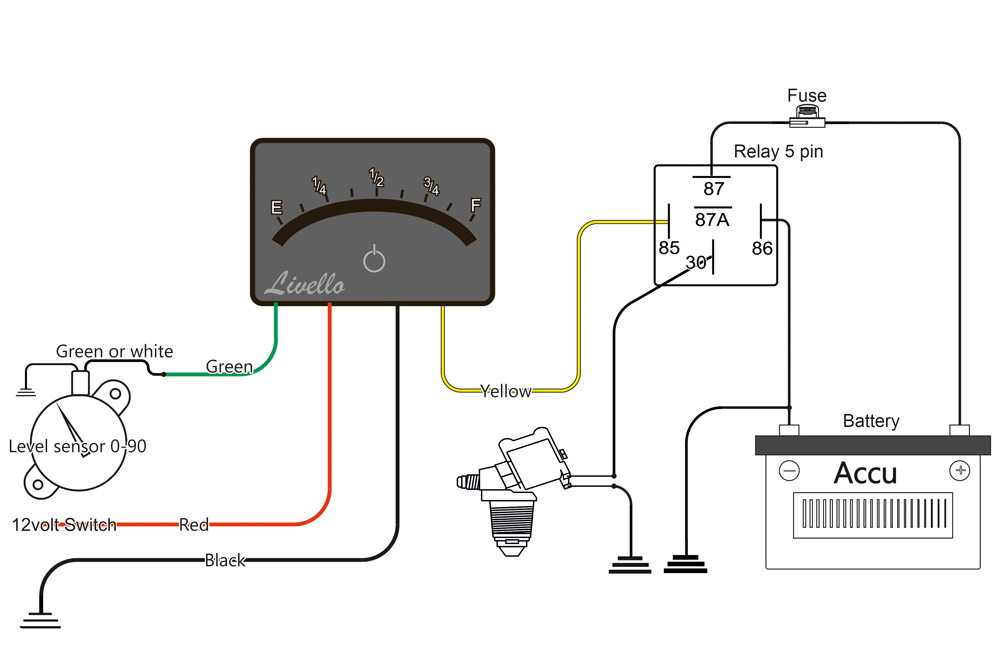
- Check if the wiring is properly connected. Often the wiring from the LED indicator (display) to the tank sensor is incorrectly connected or interrupted. In that case, the LED indicator (display) senses infinite resistance and will continuously show FULL. It could also be that the other wire from the tank sensor, which should be connected to ground, is interrupted. So also check this carefully. Check the complete wiring by measuring the electrical resistance from the sense wire of the LED indicator to ground, taking into account the current position of the tank sensor.
If the wiring is 100% correctly connected and the tank sensor is properly mounted on the tank float, then check the tank sensor and LED indicator separately. There might be a defect in one of these components.
- Testing the tank sensor: Detach the tank sensor from the tank float (unscrewing the two small screws, and do NOT remove the entire tank float from the tank!!). By holding a magnetic screwdriver to the back of the tank sensor, you can adjust its position. Set the tank sensor to 0% content and then measure the electrical resistance with a multimeter. This should be approximately 0 Ohms. Then set the tank sensor to the full position (80%) and measure the resistance again. This should now be approximately 90 Ohms. If the tank sensor deviates significantly from these values, it is probably defective.
- Testing the LED indicator (display): Disconnect the sense wire from the LED indicator to the tank sensor and leave it unconnected. Turn on the LED indicator; it should now show FULL. Now connect the sense wire to ground (chassis) (so 0 Ohm resistance to ground). The LED indicator should now show EMPTY. NOTE! There's likely a time delay built into the level display (damping). So wait a moment to see if the level display drops to empty.
Watch this video with subtitles
This article is protected by copyright. (Partial) reproduction of this article is punishable.
Disclaimer
The information in this article is intended solely as an aid and has been compiled to align as well as possible with applicable regulations and guidelines. National regulations may deviate from this or impose additional requirements. Installers and users are themselves responsible for (having) the gas installation checked and complying with applicable local laws and regulations. Always consult a certified professional for this.
Despite the care with which this information has been compiled, there is a possibility of errors and omissions. No rights can be derived from this article. The most recent and local official standards and regulations are always leading.
In addition to this specific disclaimer, our general disclaimer also applies, the link to which can be found in the menu in the footer (page end).